Overview
Ubiquiti switching – I am deploying the non-POE lite version on a current project. This appears to be an enterprise-grade switch at a SOHO price point. Steel case, DC power option and standard console cable. Specs are comparable to long-established equipment providers.
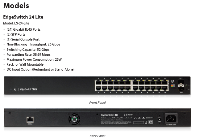
Console Connection
To access console terminal, connect console rollover cable to console port on the rear of the switch.
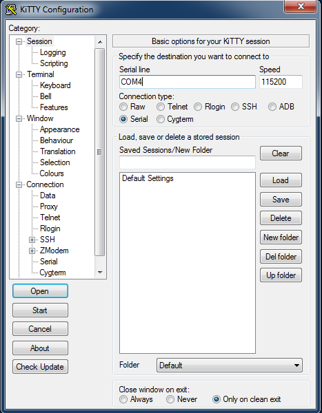
Settings
Speed 115200
Data bits 8
Parity NONE
Stop Bits 1
Flow Control NONE
You will need a USB to Serial adapter for most modern computers. Use Device Manager to determine COM port.
I received the following scrambled output while using an HL-340 USB to Serial Adapter…
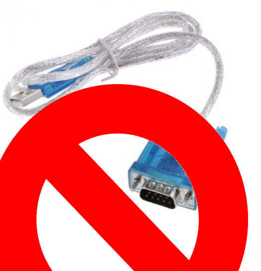
CH▒▒
▒s[n▒▒H▒▒H▒7▒▒▒▒▒H▒▒H▒7▒▒▒▒▒
I used my Trendnet adapter and it worked.
User:ubnt
Password:ubnt
(UBNT EdgeSwitch) >en
Password:ubnt
(UBNT EdgeSwitch) #terminal length 0
(UBNT EdgeSwitch) #show run
Show Interface Information
(UBNT EdgeSwitch) #show interfaces status all
Setup SSH
Generate the crypto key for SSH.
(UBNT EdgeSwitch) (Config)#crypto key generate rsa
(UBNT EdgeSwitch) (Config)#crypto key generate dsa
Make sure they are both present. Disable Version 1.
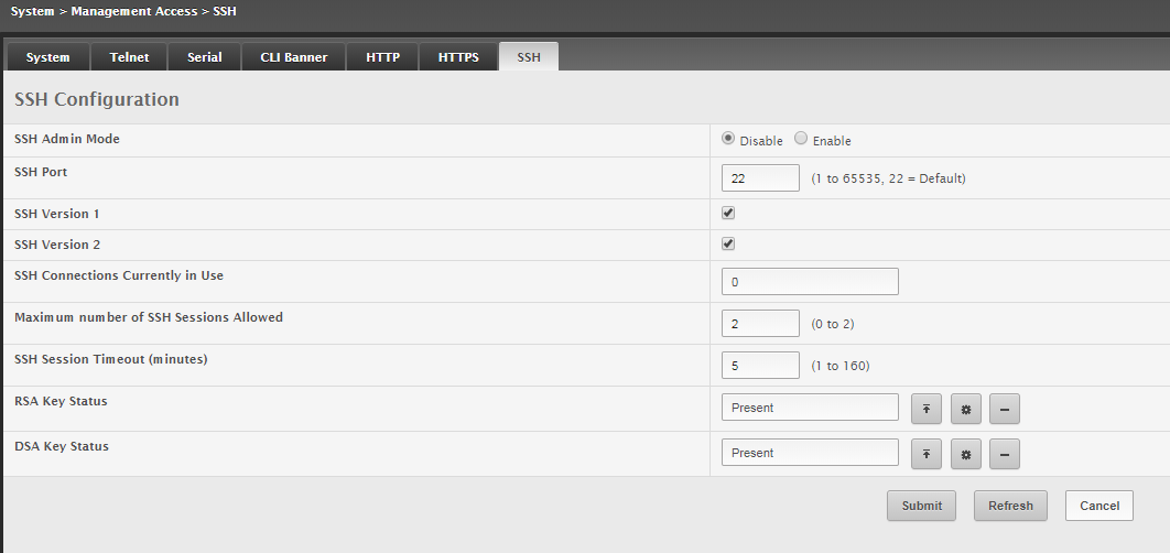
Here are some CLI commands for setting up SSH.
ip ssh server enable
ip ssh protocol 2
(UBNT EdgeSwitch) (Config)#show ip ssh
Administrative Mode: …………………….. Enabled
SSH Port: ………………………………. 22
Protocol Levels: ………………………… Version 2
SSH Sessions Currently Active: ……………. 1
Max SSH Sessions Allowed: ………………… 2
SSH Timeout: ……………………………. 5
Keys Present: …………………………… DSA RSA
Key Generation In Progress: ………………. None
CLI Write Memory To Save Config
(UBNT EdgeSwitch) #write memory confirm
Config file ‘startup-config’ created successfully .
Configuration Saved!
GUI Interface
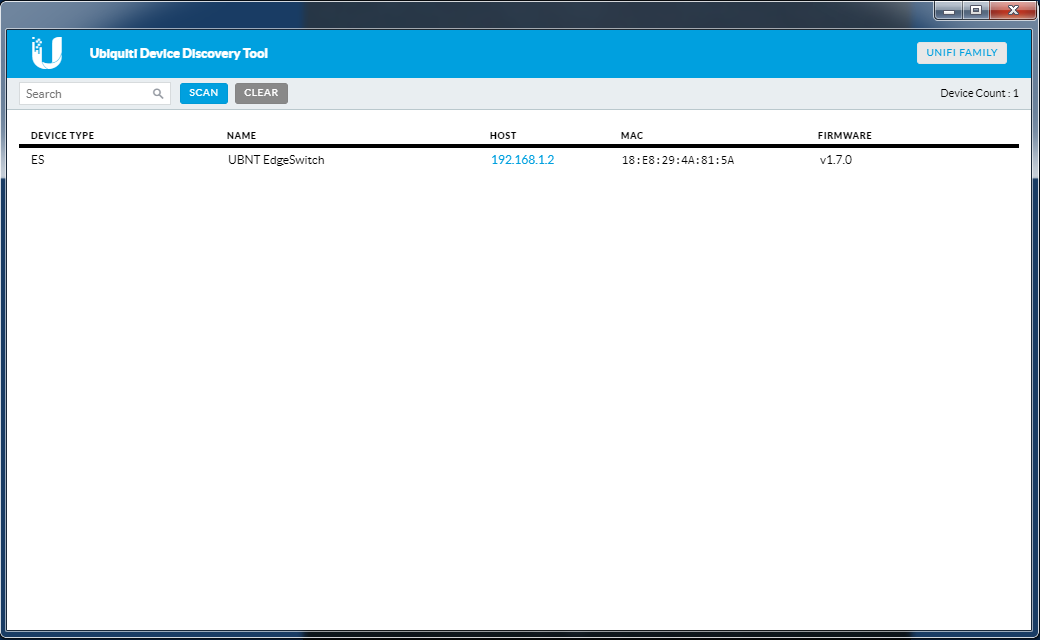
The Edgeswitch comes with a default management IP address of 192.168.1.2
There is a cool tool for chrome that allows layer2 Ubiquiti device discovery. Ubiquiti Device Discovery Tool
Once installed you can access it from chrome by copying this into the URL… chrome://apps
You will need to set your network inteface IPV4 settings to 192.168.1.X (not 2) to reach the switch. (Or your can also use DHCP.) I like to know what switch I am working on by using the default IP directly connected.)
Make sure you can ping the switch.
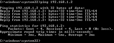
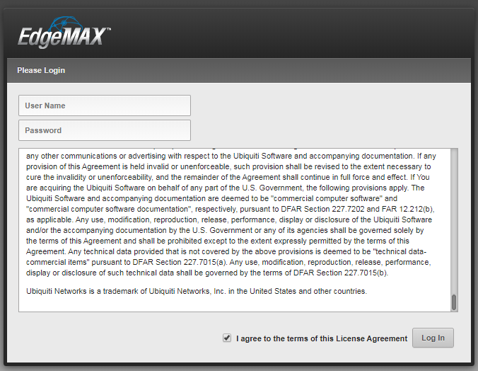
Now you can access the management webpage from a browser by opening 192.168.1.2
Enter the username and password ubnt/ubnt and accept the terms if moved to do so.
GUI VLAN Setup
Add the new VLANs. I start by entering VLAN 3. Click Add.
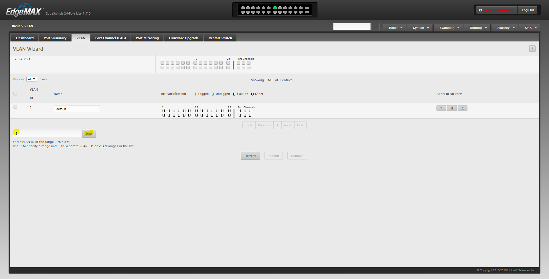
Change the name once the VLAN is added. Click Submit. Repeat for the other VLANs.
Assign Untagged, Excluded or Tagged ports by toggling between U, E and T by clicking on the letter on the VLAN row. Make sure to leave your current management port untagged VLAN 1.

In this example, I am using port 23 and 24 for untagged VLAN 3 and tagged VLAN 4 backhaul traffic. Fiber ports 25 and 26 are tagged for potential future backhaul.
Setup Rapid Spanning Tree
I prefer to use Rapid Spanning Tree. The switch comes by default set to Multiple Spanning Tree. There is no need to run MST given our topology. Effectively MST will run like RSTP but what is the point? Just run RSTP to begin with.
Switching > Spanning Tree > Switch
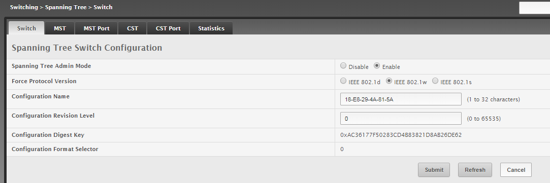
Select IEEE 802.1w. Click submit.
GUI Management IP Setup
Finding the IP address in the legacy interface can be a challenge. The bread crumb to reach the interface configuration is…
System > Connectivity > IPv4
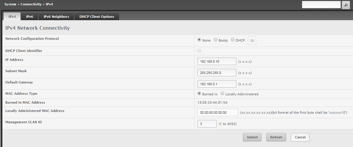
Enter the management IP address information. Select the Management VLAN ID. In this case we will use VLAN 3 for management.
WHEN YOU CLICK SUBMIT YOU WILL NEED TO CHANGE YOUR COMPUTER IP ADDRESS TO MATCH THE NEW SUBNET. YOU WILL ALSO NEED TO MOVE TO A PORT ON THE MANAGEMENT VLAN SETUP ABOVE.
Once you change your IP to the correct subnet. You will be able to log in on the new address.
Go back to the VLAN menu and program the original VLAN 1 management port to the VLAN it will used for.
Firmware Upgrade
Determine what the latest firmware revision is available on the site.
We will use ES-eswh.v1.8.2-lite.5192445.stk
Navigate to Basic>Firmware Upgrade
Select the Backup image upload by clicking the up arrow to load the firmware to the backup flash.![]()
Navigate to the folder containing the firmware file and click Open.
Click Begin Transfer button.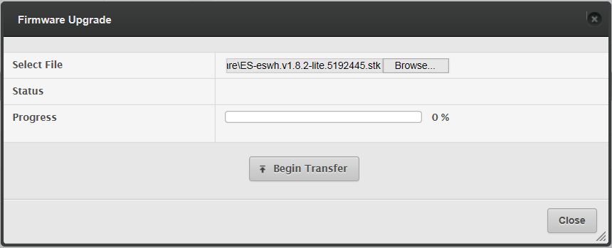
Once the Transfer is complete, click close.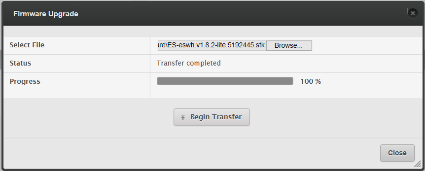
The new firmware should be in the backup location. Click the radio button to have the new firmware as Next Active. Click Submit.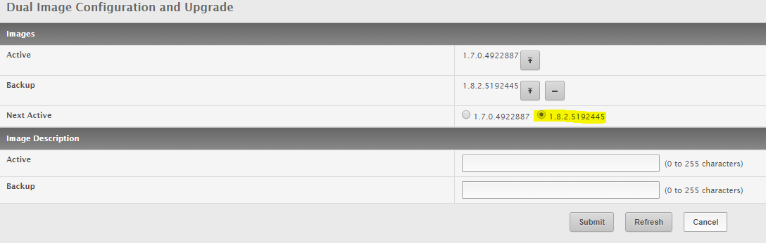
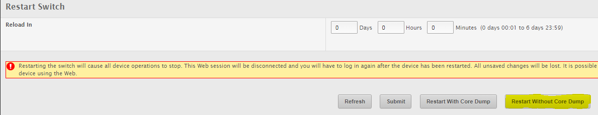
Click on the Restart Switch tab. Basic > Restart Switch
Make sure that you have saved the configuration before reloading the switch.
Click Restart Without Core Dump
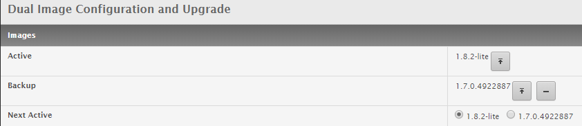
Once the device reloads, check to see if the firmware upgraded properly.
Through CLI you can issue the following…
(UBNT EdgeSwitch) #show version
Switch: 1
System Description……………………….. EdgeSwitch 24-Port Lite, 1.8.2-lite, Linux 3.6.5-1b505fb7, 1.0.0.4857129
Machine Type…………………………….. EdgeSwitch 24-Port Lite
Machine Model……………………………. ES-24-Lite
Serial Number……………………………. 18E8294A815A
Burned In MAC Address…………………….. 18:E8:29:4A:81:5A
Software Version…………………………. 1.8.2-lite
Make sure all your switches are running the same firmware.
Setting Up Time Servers
I tried using the default time servers. They did not work for me. I have always had trouble with name servers on switches. DNS resolution can be problematic even on the old school brands. I ended up loading resolved IP addresses for the servers and was able to get it working right away.
time-a-g.nist.gov…………..129.6.15.28
time-b-g.nist.gov…………..129.6.15.29
time-c-g.nist.gov……………129.6.15.30
time-d-g.nist.gov……………129.6.15.27
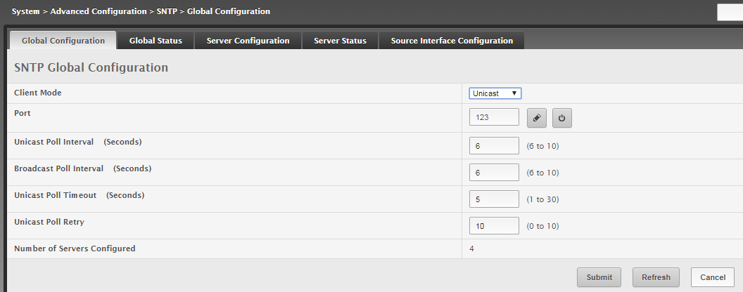
GUI Way
System > Advanced Configuration > SNTP > Global Configuration
System > Advanced Configuration > SNTP > Server Configuration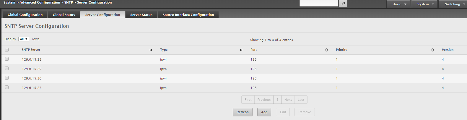
CLI Way
sntp unicast client poll-retry 10
sntp client port 123
no sntp server “1.ubnt.pool.ntp.org”
no sntp server “2.ubnt.pool.ntp.org”
sntp server “129.6.15.28”
sntp server “129.6.15.29”
sntp server “129.6.15.30”
sntp server “129.6.15.27”
clock summer-time recurring USA offset 60
clock timezone -8 minutes 0 zone “PDT”
Base Configuration
LLDP Configuration
LLDP is configured by the port on Ubiquiti switches.
To send all traffic…
interface 0/x
lldp transmit-tlv port-desc
lldp transmit-tlv sys-name
lldp transmit-tlv sys-desc
lldp transmit-tlv sys-cap
lldp transmit-mgmt
To prune LLDP traffic on port both directions…
interface 0/x
no lldp transmit
no lldp receive
To listen for LLDP packets and not transmit…
interface 0/x
no lldp transmit
Some helpful LLDP commands…
(UBNT EdgeSwitch) #show lldp remote-device all
LLDP Remote Device Summary
Local
Interface RemID Chassis ID Port ID System Name
——— ——- ——————– —————— ——————
0/23
0/24 3 18:E8:29:4A:81:5A 24 OtherSW
0/25
0/26
(UBNT EdgeSwitch) #show lldp remote-device detail 0/24
LLDP Remote Device Detail
Local Interface: 0/24
Remote Identifier: 3
Chassis ID Subtype: MAC Address
Chassis ID: 18:E8:29:4A:81:5A
Port ID Subtype: Local
Port ID: 24
System Name: OtherSW
System Description: EdgeSwitch 24-Port Lite, 1.8.2-lite, Linux 3.6.5-1b505fb7, 1.0.0.4857129
Port Description: Uplink
System Capabilities Supported: bridge, router
System Capabilities Enabled: bridge
Management Address:
Type: IPv4
Address: 192.168.0.21
Time to Live: 114 seconds