What is RF? Radio Frequency waves are an integral part of living in our modern world. The applications for wireless technology are vast. We use radio waves to communicate, cook our food, identify and track items, provide entertainment, triangulate positions, track weather, scan what lies below the surface of the earth and even scan the heavens.
So how is it that signals can be sent through space? Let’s start with the physics. Radio Frequency energy is composed of Electromagnetic waves. You might find the word strange. Can we take any concepts in physics and merge them together. Perhaps we could take gravity and mix it with energy to form grivitoenergy. All joking aside, the first physicist credited with making the connection between electricity and magnetism was Hans Christian Ørsted. It fills the Wifi Viking with pride to know that his gentleman was a good Scandinavian from Denmark.
As the story goes, Hans Christian Ørsted was discharging a current from a battery during a lecture when he noticed the needle of a compass move. He then went on to determine that magnetic lines of force circulate around a conductor as it carries a current.

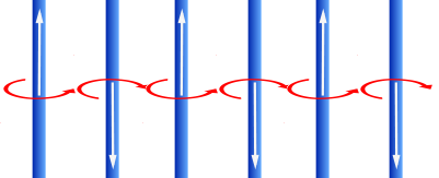
This brings us to a principle referred to as the right-hand rule. The right-hand rules states that when current flows through a conductor, a magnetic field is created which circulates around the conductor at a 90 degree angle to the conductor. These magnetic field lines circulate in the direction of your fingers when the thumb is pointed in the direction of the conventional current flow. Physics? What? I thought this blog is about Wi-Fi. What does this have to do with wireless networking?
Let’s consider alternating current. It would seem that the right-hand rule only applies to direct current. (Current that only flows in one direction.) For a thought experiment, consider what happens if we start reversing the flow. As the current changes direction, the magnet field lines run in one direction and then the other.
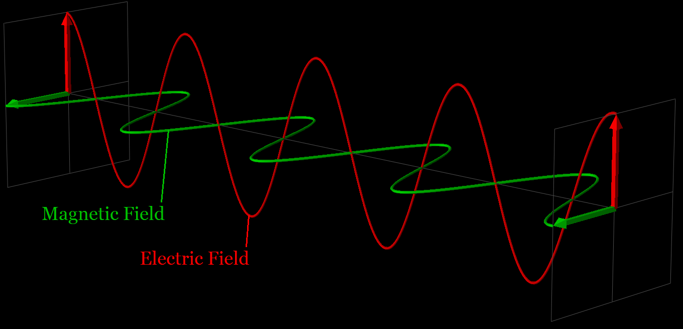
These magnetic lines of force will travel away from the conductor as a wave. An electromagnetic wave is composed of an electric field and a magnetic field. We have discussed the magnetic field with our right-hand rule thought experiment. The electric field is transmitted in the same plane as the conductor and the magnetic field is oriented at a 90 degrees angle to the electric field.
An electromagnetic field is modeled using sine waves. A sine wave represents the voltage or current measured over time. A way to visualize a sine wave is to imagine tracing the perimeter of a circle with a pencil. If you were to look at the circle from the side while you traced it, you would see the tip of the pencil traveling up and down and up and down. It would not look like a circle. If you were to trace this up and down motion on a transparent strip of material that is moving at a constant speed, you would end up with a sine wave. Hooray! Another fun thought experiment.
When we are talking about electromagnetic waves or RF waves, there are several different terms that are used to describe the waveform.
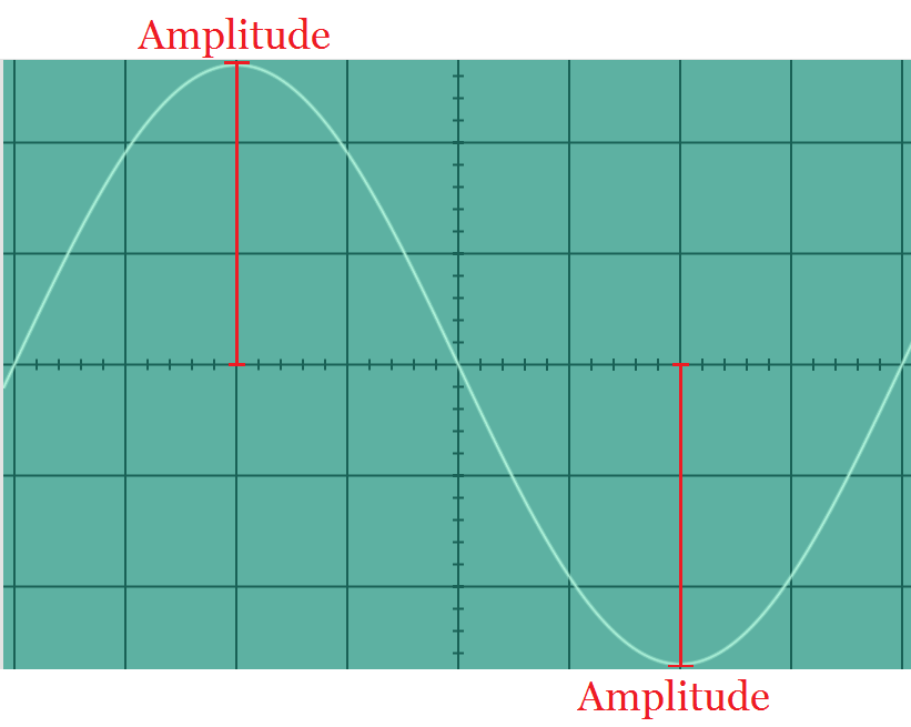
Amplitude = The maximum departure of the value of an alternating current or wave from the average value. This is the strength or height of the wave. The maximum or minimum value of the amplitude is referred to as peak.
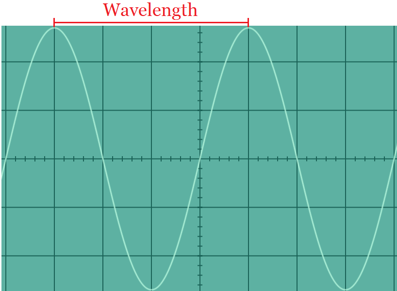
Wavelength = The distance between corresponding points of two consecutive waves. The distance over which the wave’s shape repeats. The is often referred to using the Greek letter λ (Lambda).
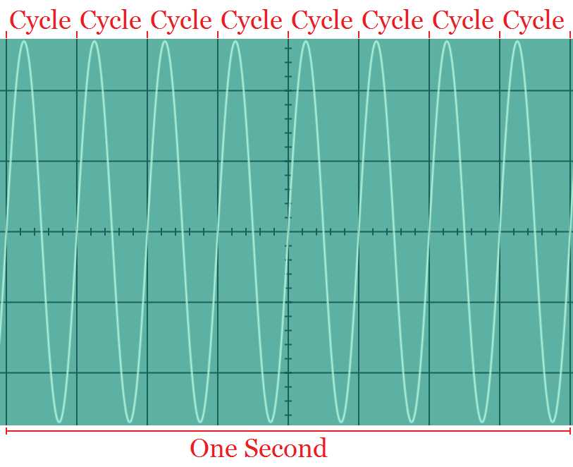
Frequency = The rate at which something occurs or is repeated over a particular period of time or in a given sample. Normally RF waves are measured in cycles per second or hertz. For the example below we will assume that each vertical division represents 125 ms. All eight squares represent one second. The frequency of this signal is eight cycles per second or eight hertz.
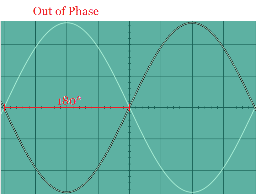
Phase = the relative position of two different waves at a specific point in time. The phase difference is measured on the zero axis between two corresponding points on the waveform. Here is an example of two waveforms 180 degrees out of phase. In this orientation, the waves will cancel each other out.
Now that we have gone over the different properties of waves, we can discuss how these different methods are used to encode data onto the waveform. Wireless communications have been accomplished using amplitude modulation, frequency modulation, and phase modulation. This process of encoding bits onto a waveform is known as keying.
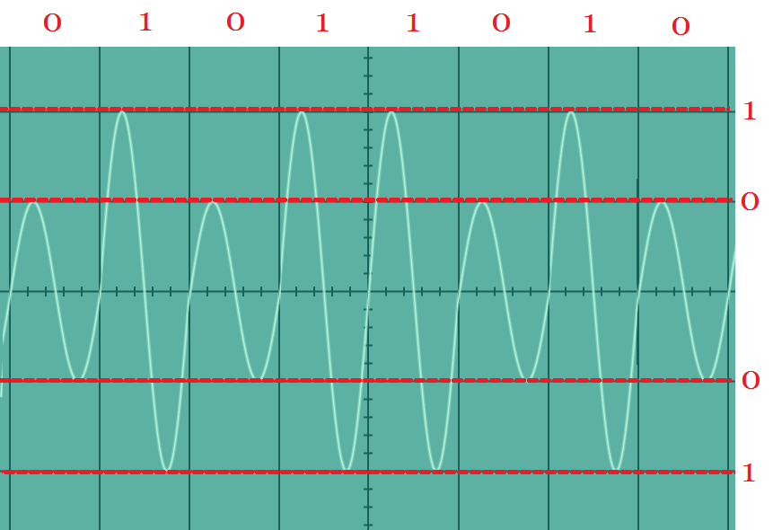
Amplitude shift Keying = the amplitude of the waveform is varied over a set period of time to indicate either a 1 or a 0. One amplitude level is one state and another amplitude value is another state. The image below has a value of 01011010.
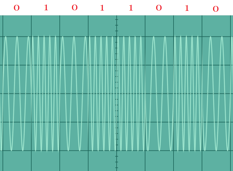
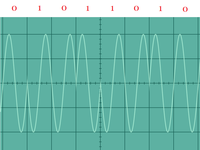
Frequency shift keying = the frequency of the waveform is varied over a set period of time to indicate either a 1 or a 0. One frequency represents a 0 and another frequency represents a 1. The image below has a value of 01011010.
Phase shift keying = the phase of the waveform is varied over a set period of time to indicate either a 1 or a 0. No phase shift represents a 0 and a phase shift represents a 1. The image below has a value of 01011010.
These different basic modulation keying methods can be complicated to include additional levels, frequencies and degrees of phase shift. Quadrature Amplitude Modulation (QAM) uses amplitude and phase modulation to encode data onto the waveform.
Thank you for watching my video today. Skål. Here’s to all you network engineers and anyone who is interested in Wi-Fi out there. Good luck building your wireless networks. This has been Bryan Noe. Have a wonderful day.